Establish TCP Socket with IP address and port number specific to course.
Continuously send heartbeat messages at 1Hz with message ID and task specific information using format unique to each task.
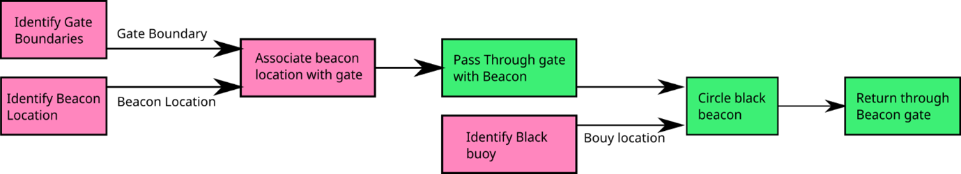
Task 2 – Entrance and Exit Gates
Identify the gate boundaries – use of lidar to recognize the shape and position of buoys, use of camera to recognize color
Identify the beacon’s location – use of hydrophones and ADLink to find direction of signal with required frequency
Associate beacon’s location with a particular gate – correlate lidar, camera and ADLink data to reflect position of required gate. Send position information to control system.
Pass through gate associated with the beacon – use control system and path finding algorithm to propel vessel in correct direction between buoys.
Identify black circle buoy – Use of lidar to recognize shape and position of black buoy, use of camera to recognize the color
Circle black buoy – use control system and path finding algorithm to propel vessel in correct direction around the black buoy
Return through same gate as entered
image courtesy of Heath Eickhoff
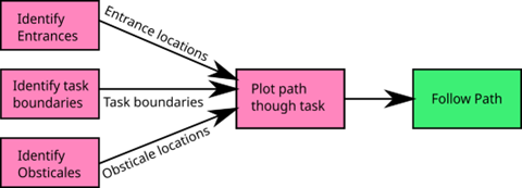
Task 3 – Follow the Path
Task entrances and exits
Recognize the pair of white buoys as start gates – enter between them
Identify course boundaries by green and red buoys
Locate positions of the green and red buoys – must stay to the left of the green markers, must stay to the right of the red markers
Identify obstacles by black buoys
Locate position of black buoys – must avoid them while meeting the above criteria
Plot path through course avoiding obstacles
Using pathfinding algorithm
Follow previously created path
image courtesy of Heath Eickhoff
Task 4 – Wildlife Encounter – React and Report
Identify creatures
Determine creatures’ locations
Circle platypus in clockwise direction
Circle Turtle in anti-clockwise direction
Report data back to the judges
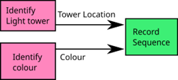
Task 5 – Scan the Code
Sequence of lights will consist of three stages separated with a long black pulse. Each stage contains a pattern of three lights with no colour appearing twice in a row.
Identify light tower – travel to light tower and position vessel so cameras have clear view of LED panel
Identify light colour – recognize red, blue and green colours using cameras
Record sequence of lights – store colours recognized into control system to be repeated later
image courtesy of Heath Eickhoff
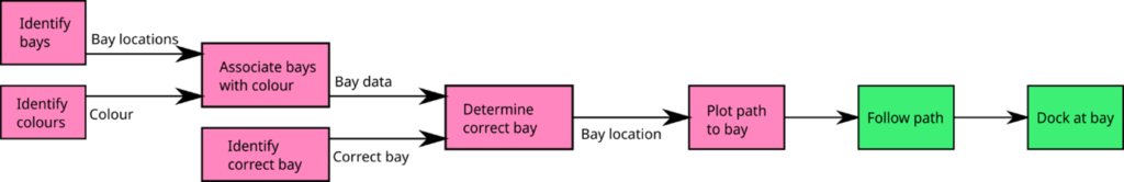
Task 6 – Detect and Dock
Identify bays
Use the lidar to recognize the rectangular shape of the light panel, and the approximate size of 1.5×1.5m base dimension sitting in the water
Identify colors
Distinguish between red, green and blue panels on the docks
Associate bays with a color
Recognize position of the panels with the position of their respective docks and color
Identify correct dock to using information gathered from another task (probably Task 5)
Plot path to correct bay
Follow path to bay
Dock at bay
image courtesy of Heath Eickhoff
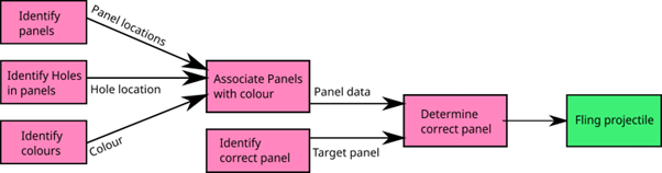
Task 7 – Find and Fling
Identify panels
Identify holes in panel
Identify colours
Associate panels with a colour
Identify correct panel to using information gathered from another task (probably Task 5)
Fling projectile through either hole in the correct panel
The TopCat USV has multiple communication systems used to connect between system actuators, radio communications and ROS topics. At the core of this system was the Core Board, a microcontroller system that connected RF teleop, CAN messages and ROS communications. Together these boards had the following functions:
Communicate with the teleoperation system using MAVLINK messages over the 900MHz radio link
Communicate with the Kokam batteries using CAN
Communicate with the Actuators using CAN
Communicate with the higher level autonomy package using ROS topics
Control low-level functions including deployer operation and battery switching
Information logged to the autonomy system includes battery voltage and temperature, max and min cell voltages, battery currents, motor speed, temperature, and current draw. The autonomy system can control battery state, motor actuation, and deployer raise and lowering using ROS topics.
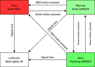
A second board with a modified firmware called the kill board was tasked with:
Control of motor isolation relays
Control of the vehicle status light
The core and kill boards implemented a state machine, moving between linkloss, stop, manual and, auto modes under the control of their respective remotes shown below.
image courtesy of Jonathan Wheare
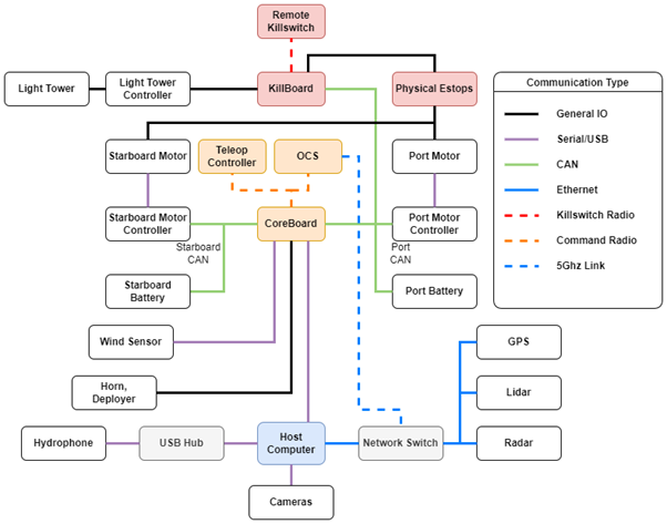
TopCat uses three communication buses, Ethernet, Universal Serial Bus (USB), and Controller Area Network (CAN) bus. Communication with the battery and engine modules is across CAN while sensors are connected via a combination of Ethernet and USB. USB devices are directly connected to the host computer through a USB hub. An onboard Ethernet switch maintains network communications on the boat, with a direct line of communication to the shore via a 5Ghz long range antenna. While CAN data, both a port side and starboard bus, is interpreted via the core board microcontroller into USB communication with the host computer.
image courtesy of Daniel Philbey
Communication channels from vessel to shore were selected based on legal and operational requirements. For teleoperation and remote kill switch communications, two 900MHz radio modem nets were selected. Australia and the USA both permit use within the 900MHz Industrial Scientific Medical (ISM) band, though Australia’s ISM frequency allocation is smaller than that of the USA. Therefore, the radio modems are compliant with both USA and Australian regulations. These radios were tested with a spectrum analyser and found to be within the expected frequency range.
For data transfer and high bandwidth communications a point-to-point 5GhZ Wi-Fi link was used. This system uses two Ubiquiti Rocket M5 modems with an Omni-directional antenna on TopCat, and a directed antenna for the Operator Control Station. The system can be configured for use around the world and is set up to meet both USA and Australian standards.
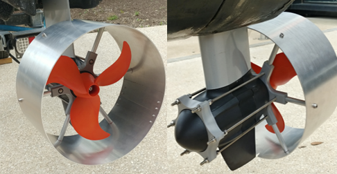
The RobotX 2022 competition required the addition of propeller shrouds on the vessel as a safety feature. Its main use is in the prevention of injury from active propeller blades for personnel around the boat. Due to the age of the Torqeedo motors currently installed on the boat, it was difficult to source propeller shrouds as Torqeedo updated their motor design since the existing motors were acquired. Therefore, it was decided that the shrouds would be designed and manufactured in-house at Flinders University.
The overall design of the shroud is an adaptation of the current line-up of propeller guards offered by Torqeedo. An absence of accurate Computer Assisted Drawing (CAD) models of the motors meant measurements of the motors needed to be taken. This was done through scanning the motor and 3D printing prototypes to ensure the shroud accurately fitted the motor.
After analysing some options, the final design comprised of a separate rolled aluminium tube that would be screwed onto an internal PVC bracket. The shroud was manufactured with water and corrosion resistance in mind therefore the fasteners were all 316 stainless steel or aluminium, this can be seen below.
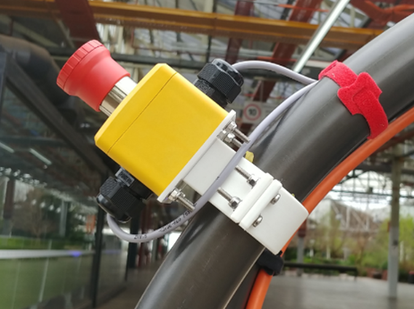
Emergency Stop System
Four mechanical e-stops are required on TopCat for it to pass the safety regulations of the competition. Due to the age of the previous e-stops, it was decided that they would be replaced and four new IP67 estops would be installed onto the vessel. The old e-stop mount had the issue of fasteners that were difficult to access, and thus the decision was made to redesign the old mounting system. The new design focused on making the nuts and bolts more accessible and included a new face plate, made of acetal, used to make the new estops more readily changeable in the future. This was done by mounting the e-stop onto the plate instead of the directly onto the bracket. An emphasis on corrosion resistant fasteners was also made in this area, therefore the fastener material was G316 stainless steel.
The new e-stops are IDEM e-stops designed for surface mount and rated for IP67. M20 cable glands were used on the e-stops to better seal and protect the connections from the environment. The new front e-stops are connected in series, with the aft e-stops to the electrical box. All new e-stops have been installed and were confirmed to be in a functional state.
Estop were mounted using maritime grade G316 stainless steel bolts, to protect against degradation due to weather, and held together with nyloc nuts to protect the connection against vibrations.